Pneumatic Metallographic Mounting Press
Clean, simple actuation from an existing compressed-air supply — a practical architecture for routine laboratory mounting where adequate plant air is available.
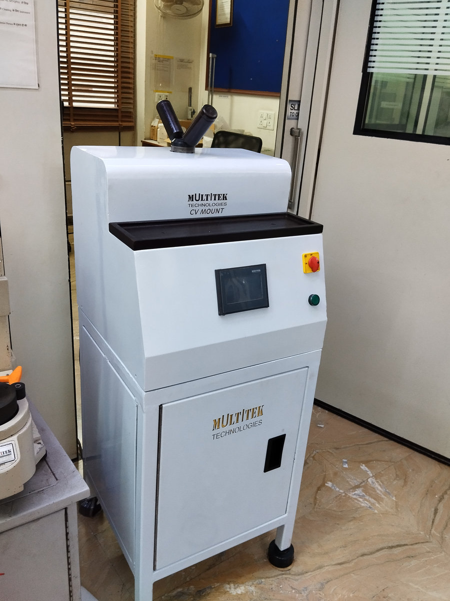
Who it suits
- Laboratories with a reliable compressed-air supply
- Routine metallographic mounting where actuator force sizing is practical
- Teams that value simple maintenance without hydraulic oil in the lab
- Quality and inspection departments running steady daily volumes
Why choose this architecture
- No hydraulic oil: nothing to leak, sample environment stays clean
- Fewer wearing parts in the force train — straightforward servicing
- Quiet in operation apart from air exhaust
- Force is generated on demand from plant air — no powered pump idling
Limitations and trade-offs
- Available plant-air pressure and mould diameter determine the actuator bore required
- Shared or unstable air supplies need sizing and pressure-control review
- Large moulds or high target pressures can make pneumatic packaging impractical
Utilities and installation
- Stable plant compressed air with adequate pressure and flow for the selected actuator
- Electrical supply matched to the heater and controls
- Cooling-water connection or a confirmed closed-loop arrangement where selected
Operational concept
Plant air acts on a large-bore cylinder; the piston concentrates that force onto the much smaller mould cross-section, multiplying pressure by the square of the diameter ratio. For example, the ideal calculation can convert a 6 bar line into roughly 250 bar at a 30 mm mould face when the actuator is sized accordingly. This is an engineering sizing example, not a published machine capability. The physics — and its limits at larger mould diameters — are covered in the pressure guide.
Configuration possibilities
- Single or multiple cylinders for higher throughput
- Fixed, HMI-adjustable or recipe-controlled pressure and temperature
- Standard or fast-cycle heating; cooling from fan-assisted to closed-loop water
- Bench-top format or integrated workstation with storage and enclosure
- Standard or custom mould tooling, subject to force and tooling review
Detailed technical specifications (dimensions, electrical load, cycle data) are defined per configuration and confirmed during engineering review — Mouldz does not publish generic catalogue values that may not apply to your machine.
Reference configuration from Multitek
Pneumatic reference architecture
Best suited to: Routine laboratories with stable plant air and a force requirement that fits a practical pneumatic actuator.
- Single- or multi-station mechanical layout
- HMI-adjustable or recipe-controlled cycles by configuration
- Water-cooled and workstation options by configuration
- Actuator sized from plant air, mould diameter and target mould-face pressure
Reference capabilities describe the cited configuration, not every machine. Final specifications are confirmed against the customer RFQ.
Verify on Multitek mounting press familiesCommon questions
- What air supply does a pneumatic press need?
- Enter the pressure and stability available at the installation point. Lower or unstable plant-air pressure does not create a universal pass/fail threshold; it requires actuator-sizing, flow and pressure-control review for the selected mould diameter.
- Can a pneumatic press reach 250 bar mounting pressure?
- In principle, yes: the machine multiplies line pressure by the cylinder-to-mould area ratio. Whether a specific configuration can do so depends on its actual bore, losses, mould diameter and regulation, so capability is confirmed during engineering review rather than implied by the architecture alone.
- Is the mounting pressure the same as my air line pressure?
- No — the air line pressure drives the actuator; the effective mounting pressure at the specimen is set by actuator force divided by mould area. The configurator asks for both values separately so nothing is lost in translation.